Best Radar Reflector for Sailboats: Active vs Passive
A marine radar reflector for sailboats is a simple idea with messy real-world results: make a skinny, low-RCS sailboat look “bigger” to ship radar. It can help, sometimes a lot, but only when you respect the physics and mount it like you actually want it to work offshore, not just look reassuring at the dock.
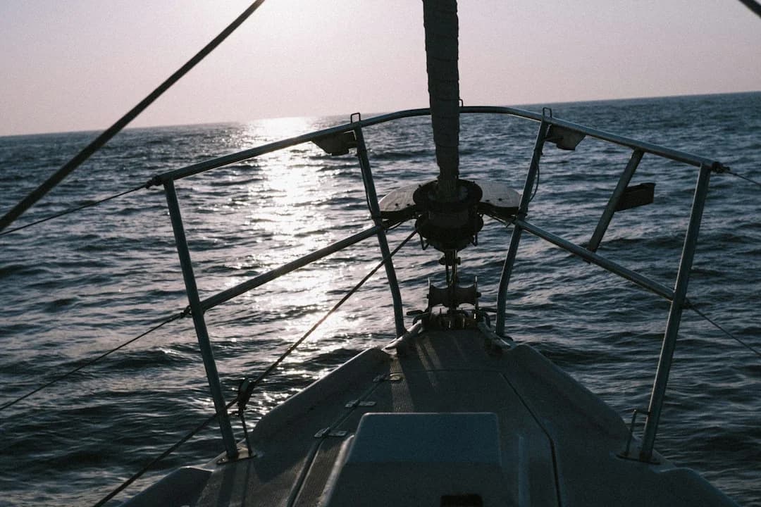
Photo by David Ramírez on Unsplash
Radar Reflectors 101: RCS, X‑Band vs S‑Band, and Limits
How ship radar “sees” a sailboat: radar cross section (RCS)
Radar doesn’t “see” fiberglass; it sees energy that bounces back to the scanner, and it judges you by radar cross section (RCS). In plain language, RCS is how big you look on radar, measured in square meters (m²), even if you’re obviously not shaped like a square meter of anything. A sailboat hull is narrow, rounded, and low, so its echo is often intermittent—more like a flickering light than a steady beacon—especially once you add heel, pitch, and a wet sea surface.
That’s why ships can get inconsistent paints on yachts even when the watchkeeper is doing everything right. Your rigging helps sometimes (stays can act like reflectors), and hurts other times (shadowing and weird scattering). The result is a target that can pop in and out, particularly inside a few miles where sea clutter and wave tops compete for the same pixels.
Why X‑band favors small reflectors (and S‑band doesn’t)
Most marine radars you’ll meet are X‑band around 9.41 GHz (about 3.2 cm wavelength) and S‑band around 3.05 GHz (about 10 cm wavelength). Passive reflectors that are physically “small” compared to the wavelength tend to look better on X‑band than S‑band, because the reflector’s geometry is closer to the scale the radar can use efficiently. That’s why a modest octahedral radar reflector can produce a usable echo on X‑band, yet do very little on S‑band unless it’s physically large and well oriented.
You’ll often hear an IMO/SOLAS-flavored benchmark tossed around: roughly 10 m² RCS on X‑band as a “good detectability” discussion target. Treat that as a reference point, not a promise; many small passive reflectors fall below it in real-world orientations, especially when heeled. If a product claims “SOLAS-type” performance but can’t show ISO 19018 results, assume the claim is optimistic.
What reflectors can’t fix: watchkeeping, clutter, and geometry
A reflector is not a collision-avoidance system; it’s one layer in a stack. COLREGs / USCG Navigation Rules Rule 5 (Look-out) and Rule 7 (Risk of collision) are blunt about using all available means, including radar, to assess risk. Your job doesn’t end because you hung shiny aluminum in the rigging, and the ship’s job doesn’t end because they have ARPA.
Also, reflectors can’t negotiate geometry. If your reflector is low (say 3–4 m above the water), behind a reefed genoa, and the sea is up, you’re asking it to outshout clutter with a weak return. The main categories you’ll see are classic octahedral plates, tubular/trihedral arrays marketed as wide-angle, inflatable reflectors for temporary use, and active radar reflectors a.k.a. Radar Target Enhancers (RTE) that receive a pulse and transmit a stronger reply.
Do Marine Radar Reflectors Work Offshore? Real‑World Performance Drivers
Mounting height and sea clutter: getting above the noise
Offshore, sea clutter is the villain that rarely shows up in marina demos. At short-to-medium ranges—think 1–3 NM—wave tops can mask a low, weak target even on a good X‑band set, especially when the ship’s gain and clutter controls are tuned for finding other ships, not yachts. This is why radar reflector mounting height matters as much as reflector type.
In practice, I aim for 4–6 m above the waterline on smaller yachts if that’s all the rig allows, and 8–15 m on taller offshore rigs when I can do it without creating a maintenance nightmare. Height improves line-of-sight, but it also helps the return stand out against the surface mess. If you’re planning a night transit across a traffic lane, plug your route into a tool to check the nautical miles for your planned route and then treat the “time spent in the lane” as a forcing function: the longer you’re exposed, the more you should care about consistent radar detectability.
Heel angle, pitch, and mast flex: why returns come and go
Passive reflectors are geometry-dependent, and offshore geometry is never stable. A classic octahedral radar reflector is built from corner reflectors that work best when they’re aligned so the incoming energy gets bounced back toward the source. Put the boat at 20–25° heel, add a bit of pitching, and those corners rotate out of their sweet spots—so the ship sees you strongly on some bearings and poorly on others.
This is where marketing language like “no heel loss” needs to be treated like a weather forecast from someone selling you umbrellas. If a manufacturer cites ISO 19018:2015 test results (not just “meets ISO”), that’s at least a measurable claim. Without that, assume performance swings and plan accordingly.
Shadowing by sails and rigging: the “radar blanking” problem
Sails and mast sections can block or distort radar energy depending on relative bearing. A big overlapping genoa can hide gear mounted too far forward, and a fat mast section can create a shadow cone on certain headings. Spreaders, running rigging, and even a stainless radar pole can produce odd reflections that confuse the return, particularly when the contact is at a low relative height and close range.
Calm-harbor tests tend to flatter passive devices because the boat is upright, range is short, and clutter is minimal. Offshore, consistency beats peak “best case” returns every time. If you sail at night, in fog, or in shipping lanes, an active radar reflector often earns its keep simply by producing a more repeatable target across headings.
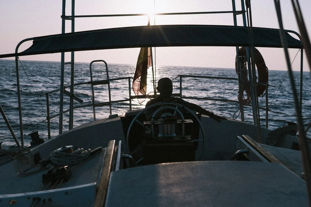
Photo by David Ramírez on Unsplash
Passive Radar Reflectors Compared: Octahedral, Wide‑Angle, ISO 19018
Octahedral corner reflectors: size, orientation, and tradeoffs
The octahedral radar reflector is the old standard because it’s simple and, when oriented correctly, it works reasonably well on X‑band. Size matters: common classes are about 200 mm (8 in), 300 mm (12 in), and 450 mm (18 in) plate units. Bigger plates generally mean higher potential RCS, but also more windage, more halyard slap risk, and more unpleasant noises at 0200 when you’re trying to sleep.
Orientation matters more than most people admit. Some housings are meant to be mounted “rain-catcher” style (points up like a diamond), others “catch-basin” style (square-ish presentation), depending on internal geometry. If you guess wrong, you can reduce your average return over 0–360° headings, which is the whole point of carrying the thing.
“Wide-angle” and tubular designs: what to verify
Tubular/trihedral arrays and “wide-angle” housings try to maintain a usable return across more angles and a bit of heel. Sometimes they do; sometimes they’re just a different compromise packaged in nicer plastic. The serious way to evaluate them is to look for ISO 19018:2015 documentation: test method, frequencies (X‑band and/or S‑band), and plots or tabulated RCS results across angles.
Watch the language. “SOLAS compliant” is often used loosely for recreational products; SOLAS is a regulatory framework, not a product feature sticker. If the only proof is a vague brochure line, assume it’s marketing, not engineering.
Durability and mounting loads: housings, plates, and corrosion
A passive reflector lives aloft in UV, salt, vibration, and bird politics. Typical weights run about 0.5–2.5 kg, and that weight matters: it increases mast vibration loads and can loosen hardware over time. For mounting, you’ll commonly see 25–40 mm (1–1.5 in) U-bolt clamps on poles/spreaders, and through-bolting with backing plates when you attach to thinner mast walls.
Aluminum plates plus stainless fasteners is a classic recipe for dissimilar-metal corrosion if you don’t isolate properly. Use isolation pads, barrier compounds, and re-check fasteners seasonally. If you want “install and forget,” boating may not be your sport.
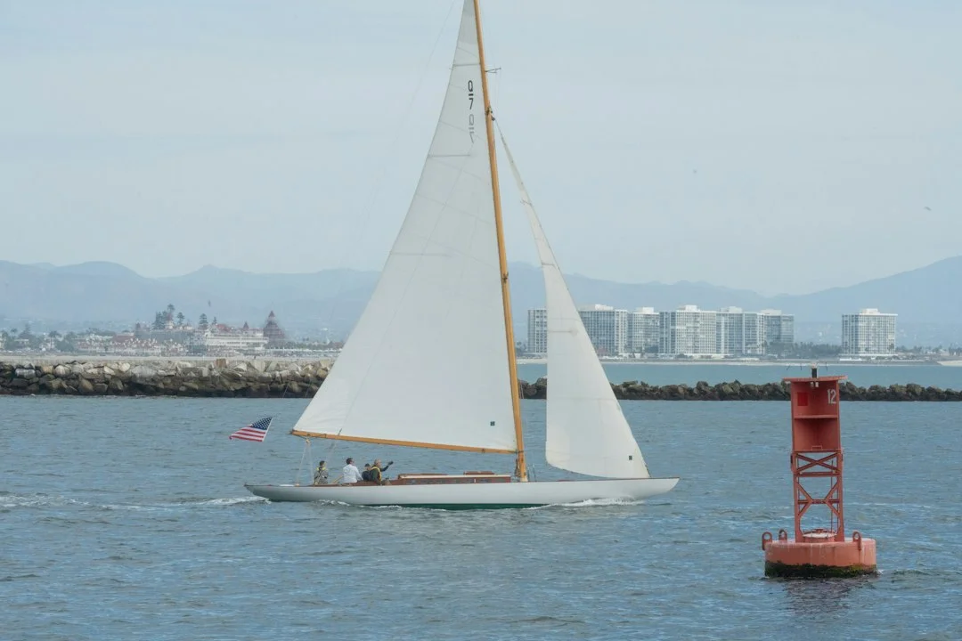
Photo by Diwei Zhu on Unsplash
| Passive option | Size class | Typical weight | Windage / rig interference | ISO 19018 claim to look for | Best mounting position |
|---|---|---|---|---|---|
| Classic octahedral plates | 200 / 300 / 450 mm | ~0.5–2.5 kg | Higher with 450 mm; can slap halyards | “Tested to ISO 19018:2015” with RCS plots | Mid-to-upper mast, clear of headsail leech |
| Housed octahedral (plastic case) | 300–450 mm equivalent | ~0.8–2.5 kg | Less snaggy; still windage aloft | ISO 19018 method + minimum criteria statement | Mast mount on bracket, away from spreaders |
| Tubular / trihedral array (“wide-angle”) | Varies | ~0.6–1.8 kg | Often lower snag risk; check vibration | ISO 19018 evidence across angles | Upper mast or dedicated pole, minimize shadowing |
| Inflatable reflector | Varies | ~0.3–1.0 kg | Low weight; shape stability can suffer | Rare; demand real test data | Temporary hoist (passage/fog), not permanent |
Active Radar Reflectors (RTE): Reply Logic, Power Budget, Failure Modes
How an RTE differs from “just reflecting” energy
An active radar reflector—often called a Radar Target Enhancer (RTE)—isn’t trying to be a better mirror. It listens for incoming radar pulses, processes them, and transmits a stronger reply so the other radar sees a more consistent, more obvious target. In practice, an RTE can reduce the “now you see me, now you don’t” behavior that plagues passive reflectors when you’re heeled and bouncing.
Active units tend to shine when your natural RCS is poor: low freeboard, carbon rigs, cluttered seas, and long nights near commercial traffic. If you’re frequently crossing shipping lanes, I rate consistency over a single impressive return on a calm day. The ocean has a habit of scheduling your close calls for the worst possible conditions.
Electrical realities: standby draw, peaks, and daily Ah costs
Power draw is usually manageable, but you need to budget it like any other offshore load. Typical average/standby current is about 30–100 mA, with higher momentary peaks during reply bursts depending on model and traffic density. At 12 V, that’s roughly 0.4–1.2 W average class, translating to about 0.7–2.4 Ah/day if it’s on continuously, and potentially higher when you’re in a busy radar environment.
That’s not catastrophic, but it’s not free either—especially on a small house bank where 20 Ah here and there is the difference between refrigeration and warm beer. When you use calculate the distance between ports for passage planning, add an “electronics budget” column next to distance and time. It’s a simple habit that prevents a lot of dumb decisions after day three.
Installation and reliability risks: water ingress, RF placement, lightning
Active gear fails in boring ways: water in the housing, corroded connectors, chafed coax/power in the mast, and lousy deck glands. Most “mystery faults” are installation faults, not bad electronics. Follow ABYC E‑11 practices: support wiring, protect it from chafe, fuse it correctly, and avoid letting connectors sit in water because your drip loop was “optional.”
Because active enhancers are RF devices, check FCC/CE compliance markings and obey manufacturer separation guidance from other antennas. Keep sane spacing from VHF where possible (I try for ~1 m / 3 ft), and don’t mount it where it’s shadowed by a radar scanner or buried behind a sail track. Lightning? Route wiring thoughtfully and avoid creating new chafe points and sharp bends; just don’t pretend any of this makes you lightning-proof.

Photo by Quentin Baret on Unsplash
Where to Mount a Radar Reflector: Height, Location, Orientation
Choosing height using radar horizon math (route planning use case)
Height is the cheapest performance upgrade you can buy, and it works for both passive and active units. The radar horizon rule of thumb is: distance to radar horizon (NM) ≈ 2.23 × √(height in meters). Put a reflector at 10 m above the waterline and you get about 2.23 × √10 ≈ 7.0 NM to the horizon from your end, before you add the ship’s antenna height.
That’s why mounting at 4–6 m on a small yacht is “better than nothing,” but it won’t perform like an 8–15 m placement on a taller rig. When you plan routes—especially traffic separation scheme crossings—use Breezada’s sea distance calculator to estimate how long you’ll be exposed to higher collision risk zones. Then decide if “mid-mast because it was easy” is actually a decision you want to defend later.
Avoiding shadowing: sail plan, mast section, and hardware conflicts
Fore-and-aft placement matters because sails are big radar blankets. A reflector hidden behind a fully deployed genoa is a reflector you’re carrying for emotional support. On masthead sloops, I usually prefer the reflector slightly aft of the mast section and clear of the headsail leech, while still avoiding being directly in the mainsail’s worst shadow zone.
Also look at what else is aloft. A fat LED tri-color, wind instruments, AIS antennas, and a VHF whip create both physical conflicts and RF interactions. Don’t cram the reflector into the one remaining square foot of mast real estate and then blame “radar physics” when it performs poorly.
Best-practice clearances: VHF, AIS, radar scanners, and rigging
A practical clearance guideline is ~1 m (3 ft) from the VHF antenna when you can manage it, plus enough separation that halyards and topping lifts can’t chafe or slap it. If you have a radar scanner on a mast bracket, don’t mount the reflector in its immediate shadow or so close that it becomes a weird secondary reflector. On boats with inner forestays (cutters), check that tacks, hanks, and staysails can’t foul the reflector when it’s blowing 25–30 knots and everyone is tired.
Orientation is the silent killer for passive devices. If the unit needs “rain-catcher” (diamond) orientation, lock it so it can’t rotate under vibration—nyloc nuts, threadlocker where appropriate, and anti-rotation features. If it’s hoisted on a halyard, use a proper bridle or stiffener so it doesn’t spin like a carnival ride in a seaway.

Photo by Peter Chirkov on Unsplash
Installation Details: Hardware, Corrosion Isolation, Wiring (ABYC E‑11)
Passive installs: brackets, vibration control, and halyard management
For passive units, the install is mostly mechanical, but “mostly” is where problems live. Use 316 stainless fasteners, and distribute loads with backing plates when you’re through-bolting thin mast walls. A typical clamp range is 25–40 mm for poles and spreaders, but don’t assume—measure the section, because “standard” ends the moment you buy a used boat.
Vibration control is not optional. A 0.5–2.5 kg reflector can work fasteners loose, and loose hardware turns into elongated holes and crevice corrosion. Manage halyards with standoffs or fairleads so they can’t slap the housing; halyard slap is annoying, but chafe through a line at the wrong moment is the expensive version.
Active installs: wire gauge, fusing, mast routing, waterproofing
Active RTEs add wiring, and wiring aloft needs to be treated like rigging: supported, protected, and inspectable. Per ABYC E‑11, size conductors for the run length and load, support them at intervals, protect at penetrations (mast partners, exit plates), and avoid sharp bends. Typical runs use 14–16 AWG marine-grade tinned copper, but confirm voltage drop for your mast height and device draw.
Overcurrent protection should be near the source, with a fuse commonly 1–3 A (manufacturer dependent). Don’t “fix” nuisance blows by upsizing the fuse until it stops blowing; that’s how you turn a wiring fault into smoke. Waterproof deck glands or mast entry fittings run about $15–$60, and they’re worth every dollar if they prevent water migration into the core of your wiring problem.
Aloft vs mast-down workflow: time, tools, and safety checks
If the mast is down, a DIY install can be 1–3 hours including clean routing and proper strain relief. Aloft, the “tool time” might be 1–2 hours, but the real time is setup, safety checks, and waiting for a weather window that isn’t lying to you. Use a two-person rule, inspect the bosun’s chair, and treat every shackle like it’s trying to ruin your month.
I’m not against going up the mast; I’m against casual mast work. If you’re tired, rushed, or improvising, postpone it. The best radar reflector for sailboat safety is the one you install without falling off the rig.
Photo by ryu _ on Unsplash
Practical tip: If you’re installing an active RTE, pull a messenger line and run one spare tinned two-conductor cable at the same time. The extra $30–$80 now is cheaper than a second trip inside the mast later.
Costs, Value, and When AIS Is the Better Spend
Budget tiers: what changes from $50 to $900+
With passive reflectors, you’re paying for size, stiffness, housing durability, and (occasionally) documented testing. Basic octahedral units can be $25–$90, but they’re often light-duty, noisy, and easy to mount wrong. Mid-grade housed passives land around $90–$200, and higher-performance passive designs are typically $200–$450, sometimes with ISO 19018 language you should verify.
Active RTEs usually run $450–$1,200, and the extra money buys electronics, sealing, and (if the manufacturer is serious) documented performance and support. The hidden cost is installation complexity and the fact that electronics have failure modes aluminum plates don’t.
Total installed cost: parts, labor, and access (mast/haul-out)
Most sailors under-budget installations because they price the device and forget everything that makes it work. Hardware can be $25–$150, wire and terminals $30–$120, and a deck gland $15–$60. Professional installation commonly lands $300–$1,200 depending on access, and if you need haul-out or crane time, add $200–$800.
If you’re planning a longer passage, use Breezada’s sea distance calculator to estimate hours underway and then ask a blunt question: what’s the cost of one avoidable near-miss in the dark? This isn’t about fear; it’s about allocating money where it reduces risk effectively.
Radar reflector vs AIS vs both: collision-avoidance layering
AIS and radar solve different problems. AIS improves cooperative visibility to AIS-equipped vessels (and to you), while reflectors improve non-cooperative detectability—especially important when a ship is using radar as the primary sensor in rain or at night. Offshore, the layered approach is practical: AIS (Class B or at least receive-only) plus a reflector (passive or active), plus disciplined watchkeeping and your own radar if you have it.
Here’s the sober reality: a ship officer may be staring at radar and not at AIS, or vice versa, depending on workload and conditions. If you can be a better radar target and a better AIS target, you’re stacking the odds in your favor.
| Budget tier | Typical items | Typical installed total | Best for | Main compromises |
|---|---|---|---|---|
| Economy passive | $25–$90 reflector + $25–$60 basic hardware | $50–$150 | Day/coastal use, occasional fog | Often low/variable RCS; easy to mount too low or wrong orientation |
| Mid passive (housed / larger) | $90–$200 reflector + $40–$120 hardware | $150–$350 | Regular coastal cruising, night entries | Windage/weight; still heel- and shadow-sensitive |
| Premium passive | $200–$450 reflector + $60–$150 hardware | $260–$600 | Offshore-capable setups wanting no power draw | Still geometry-dependent; verify ISO 19018 claims carefully |
| Active RTE | $450–$1,200 unit + $70–$250 wiring/glands + $300–$1,200 labor | $850–$2,600 | Offshore, shipping lanes, low-visibility regions | Power draw, wiring complexity, water ingress/cable chafe failure modes |
How to Validate Performance: On‑Water Testing and Maintenance
Two-boat test protocol: headings, ranges, and logging
If you really want to know whether your setup works, do a controlled test with a buddy boat that has radar and a cooperative skipper. Run 8–12 headings (every 30–45°) at two ranges, such as 1–2 NM and 4–6 NM, and log what happens. You’re looking for consistency across bearings, not the single best screenshot you can brag about at the bar.
Record conditions because they matter: sea state, rain clutter settings, gain, wind angle, and average heel. If you can repeat the same passes with the sails reefed versus full, you’ll often discover you mounted the reflector in the exact spot the genoa likes to “helpfully” block.
What to check on X‑band vs S‑band displays
Do the test on X‑band first, because that’s where most passive devices show improvement on small craft. Then check S‑band if the radar has it, especially if your sailing area includes heavy rain clutter conditions where ships may prefer S‑band. Don’t be surprised if a small passive reflector barely moves the needle on S‑band; the 10 cm wavelength is unforgiving when the reflector is small and the boat is moving.
A “good” result is earlier acquisition and fewer dropouts when you’re heeled and pitching. A mediocre result is a strong return only on a couple of headings, with long dead zones elsewhere. If that’s what you see, the fix is usually height, orientation, and shadowing—not wishful thinking.
Maintenance checklist: fasteners, sealing, and cable health
Inspect aloft at least seasonally, and again after a heavy-weather passage or rig service. Check that fasteners haven’t loosened, that anti-rotation features still work, and that isolation pads or barrier compounds haven’t degraded. For active units, inspect deck glands and connectors for water ingress, and look for chafe points where the cable exits the mast.
If you have a shunt-based battery monitor, confirm the unit’s average draw matches expectations—typically 30–100 mA class. A sudden increase or a dead flatline is a clue before it becomes a surprise. Most failures are gradual; sailors just tend not to look until they’re already annoyed.
Frequently Asked Questions
For an octahedral reflector, what orientation (diamond vs square / “rain-catcher” vs “catch-basin”) gives the best average RCS over 0–360° relative bearings per ISO 19018 test setups?
There isn’t a universal “diamond is best” rule because housings and internal plate geometry vary, but ISO 19018 testing focuses on average performance across headings and elevations, not one perfect angle. In practice, many classic octahedrals are intended to be mounted in the manufacturer-specified “rain-catcher” orientation so multiple corner sets are presented across azimuth. The correct answer is: mount it exactly as the ISO 19018-tested configuration states in the documentation, and be suspicious if the product can’t provide that configuration clearly.
How does a 20–30° heel angle mathematically change the effective corner-reflector alignment, and which passive geometries maintain usable RCS across heel better than classic octahedrals?
A heel of 20–30° rotates the reflector’s corner axes away from the incoming wave direction, so fewer corners satisfy the “energy in, energy back to source” geometry at any given bearing. You don’t need the full trigonometry onboard to see the effect; you see it as target dropouts and bearing-dependent fading. Designs marketed as “wide-angle” tubular/trihedral arrays can maintain usable returns across more angles, but the only credible way to judge is ISO 19018 data showing reduced performance valleys compared with a classic octahedral.
If my reflector is mounted at 10 m above the waterline, what is the radar-horizon limit using 2.23 × √h, and how does adding a ship’s 30 m scanner height change mutual line-of-sight acquisition range?
At 10 m, the radar horizon from your reflector is about 2.23 × √10 ≈ 7.0 NM. A ship’s scanner at 30 m has a horizon of 2.23 × √30 ≈ 12.2 NM. Add them for mutual line-of-sight and you get roughly 19.2 NM in ideal conditions, before you account for refraction variability, sea clutter, and the fact that “seeing” is not the same as “recognizing a small target in noise.”
For an active RTE drawing 60 mA average at 12 V, what is the daily amp-hour consumption and what ABYC E‑11 overcurrent protection and conductor-sizing considerations apply for a mast run?
At 60 mA (0.06 A) continuous average, daily consumption is 0.06 × 24 = 1.44 Ah/day at 12 V. Under ABYC E‑11, protect the circuit with properly sized overcurrent protection near the source (often 1–3 A, per manufacturer), support the conductor to prevent chafe, protect at penetrations, and size the wire (often 14–16 AWG tinned marine wire) to control voltage drop over the full mast run. Don’t upsize fuses to stop nuisance trips; fix the root cause.
When a manufacturer claims “SOLAS compliant,” what documentation should I look for (e.g., ISO 19018 test report, RCS plots, test frequency bands), and what wording is a red flag?
Look for ISO 19018:2015 test method details, measured results (RCS plots or tables), the test bands (at least X‑band 9.41 GHz, ideally clarity on S‑band too), and a statement of what minimum criteria were met. A red flag is vague wording like “SOLAS-type,” “meets SOLAS,” or “compliant” without a test report, lab name, or data across angles. SOLAS influences best practice, but for small-craft reflector shopping, ISO 19018-backed numbers beat brochures every time.
Conclusion
Passive reflectors can improve X‑band detectability, but their real performance depends heavily on size (200/300/450 mm classes), orientation, heel, and mounting height (4–6 m vs 8–15 m). Active RTEs typically deliver more consistent returns across headings, but you pay for that with power draw (often 30–100 mA class), wiring complexity, and more failure modes.
Mount it as high as practical with minimal sail shadowing, verify ISO 19018-backed claims where possible, install with corrosion isolation and ABYC-style wiring, and validate the setup with a structured on-water test. Your future self in fog at 0300 will not miss the money, but they will miss the second chances.
About the Author
Related Articles

Sail Trim for Beginners: Main + Jib Cruising Guide
Learn sail trim for beginners with simple main + jib settings, telltales, twist, traveler & vang. Get quick wind-based trims—read now.
By Breezada Team
Sailboat Bimini Guide: Dodger & Enclosure Choices
Learn how to choose a sailboat bimini, dodger & cockpit enclosure—materials, fit, costs, and DIY vs pro. Get the right setup today.
By Breezada Team
Code Zero vs Genoa: Jib & Spinnaker Guide
Compare Code Zero vs genoa, jib, and spinnaker by wind range and angle. Choose the right headsail for your boat—read the guide now.
By Breezada Team
Starlink Mini on a Boat: Plans, Power & Offshore Use
Learn Starlink Mini on a boat—plans, power draw, and offshore performance. Compare Roam vs Mobile Priority and get setup tips. Read now.
By Breezada Team